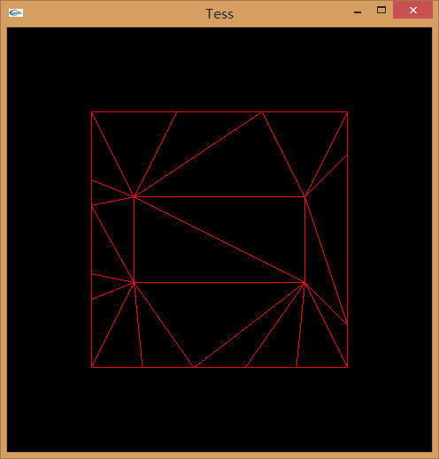

(For the isoline case, I also rendered a dot atĮach vertex so you can see where they are along the lines.) Triangle, quad, and isoline domains respectively. Here’s a video showing the tess factors animating from 1 to 64 in integer spacing mode, using the There are no smooth transitions subdivisions areĪlways equally spaced in UV distance, and we just discretely pop from one to the next. In integer spacing, also called equal spacing, fractional tess factors are rounded up to It also doesn’t exist in OpenGL.) Integer Spacing (There’s also a fourth mode, “pow2”, but I’ll ignore it here, since it’s just integer mode with anĮxtra restriction. The number of segments that a given edge or UV axis will be subdivided into, but there are three Broadly speaking, the tess factors are just The interpretation of the tessellation factors. Spacing modes (actually called “partitioning” modes in D3D, but I like the OpenGL term better) affect void ds ( in float edgeFactors : SV_TessFactor, in float insideFactor : SV_InsideTessFactor, in OutputPatch inp, in float3 uvw : SV_DomainLocation, out float4 o_pos : SV_Position ) Spacing (aka Partitioning) Modes

Here’s an HLSL snippet for a basic triangle domain shader that just interpolates positions: The barycentrics are represented by colors (UVW = RGB) in the diagram below.

The domain shader receives three barycentric coordinates, which always sum Single “inside” tess factor, which specifies the number of mesh segments from each edge Which specify the number of segments that each edge of the triangle gets subdivided into. The triangle domain generates triangular output patches. There are three domains supported by the hardware: triangle, The “domain” mode controls the shape of the tessellated mesh that will be generatedĪnd fed through the domain shader. Those relationships are shown in theĭiagrams below, and carry through regardless of which conventions you’re using, or which API.
#Tessellation shader Patch#
Is the relationship between patch UVs and tess factors. The thing that isn’t up to individual convention, but is fixed by the hardware and API definitions, Shaders, there is no canonical vertex order for patches! Different conventions for vertex orderĪre possible, which can lead to different people’s or projects’ tessellation shaders havingĭifferent mappings between vertex index and the patch UVs and tess factors. Note that because the meaning of the vertices is up to the interpretation of the hull and domain Quad patches, or 16 for bicubic patches with all the control points. Common patch sizes include: 3 for triangular patches (e.g. Vertices you want, from 1 to 32, and the meaning of those vertices is up to the interpretation of What constitutes a “patch” on the input side is pretty free-form. In OpenGL, though, it’s all tossed together in one entry (per-patch rather than per-patch-vertex). Separate entry point from the main hull shader, and it conceptually runs at a lower frequency The “patch-constant” part of the hull shader looks sort of like an extra stage of its own in D3D it has a To produce the final vertex data to rasterize. Generated vertex within the patch, and is responsible for interpolating, displacing, and what-have-you Also useful for per-patch frustum culling.ĭomain shader-post-tessellation vertex shader. Primarily responsible for setting tessellation factors, though it can also Runs right after vertex shading, and can see the data for all the When tessellation is enabled, the GPU pipeline gains two(ish) additional stages:


 0 kommentar(er)
